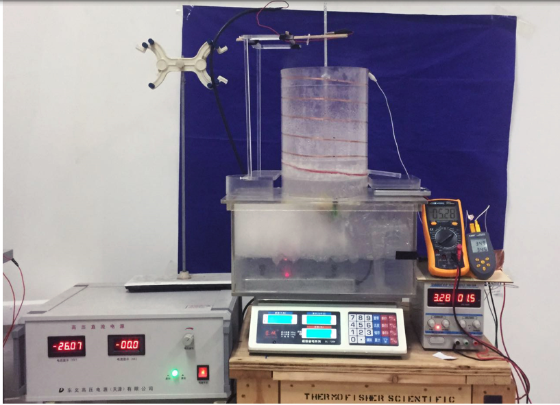
This project designed on a sophisticated water recovery apparatus for cooling towers, predicated on the principle of air corona ion wind technology. Fundamentally, this apparatus engenders an ionized airflow by administering a high voltage across electrodes of significant curvature. As the aqueous vapor emanating from the cooling tower traverses through the zone influenced by ion wind, it undergoes induced nucleation facilitated by the electric field and ionization process. This results in the formation of condensate droplets, which are subsequently aggregated along with the inherent droplets within the cooling tower's moisture content.
1. Multi-stage Parallel Honeycomb-style Water Recovery Device and Installation Schematic
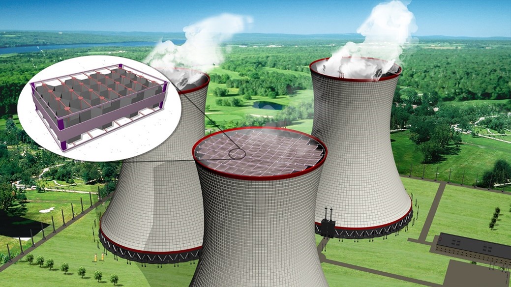
Considering the extremely large area of the top of the cooling towe, which can reach thousands of square meters, it is possible to use a parallel combination to expand the water collection device to achieve the purpose of large-area coverage. Figure below shows the design of expanding the water collection unit. First, various water collection units are combined in parallel to form a water collection module with a coverage area of about 2m × 3m. Then, each water collection module is arranged in an array to ultimately cover the entire top of the cooling tower, allowing for the recovery of water vapor from the top of the tower without omission. Since the expansion process involves direct replication of the original water collection unit, it is possible to maintain the original water collection efficiency unchanged.
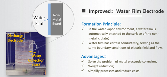
However, since the device is installed on the cooling tower, it is easily affected by water vapor, dust, etc., and the working environment is harsh, so insulation issues are particularly important. Therefore, in the above-mentioned device, we have adopted a solution of layered insulation. The conductors that connect to the high-voltage power supply are marked in red on the top surface, which is the high-voltage layer. A high-voltage layer is also symmetrically distributed on the bottom surface, and the discharge electrodes are supported on the two high-voltage layers. The middle honeycomb structure acts as the ground layer. In this way, the arrangement of high-voltage layer - ground layer - high-voltage layer is staggered, and by adjusting the height of the supports, the distance between layers can be adjusted to adapt to the insulation issues under different dirty environments.
Considering the installation location of the device, since water vapor continuously condenses during the rising process, installing the device at the top of the tower has the best water collection efficiency. Additionally, installing the device at the top of the tower allows it to fully exchange heat with the air outside the tower, which is more conducive to the condensation of water vapor and also benefits the improvement of water collection efficiency. The installation at the top of the tower can be done using a rope hoisting method. The installation at the top of the tower first requires the device to be lightweight and reliable. Although using a dome installation method is reliable, it is difficult to install, and the device is also relatively heavy. Therefore, we propose a rope rigging installation method, that is, using tensioned ropes to hoist the entire device at the top of the cooling tower. Figure below shows the installation effect of the rope rigging. Utilizing this scheme can not only reduce the weight of the device but also significantly lower the cost of manufacturing and installation.