Dynamic Simulation Testing Systems for Urban Intelligent Distribution Power Networks

We developed a hybrid digital-physical testbed for next-generation intelligent distribution networks, integrating physical equipment with real-time simulation and cloud-based monitoring. Automated scenario testing supports system-level validation across fault detection, device interaction, and remote control. The platform covers 96 test scenarios and was deployed across 12 provincial power companies.

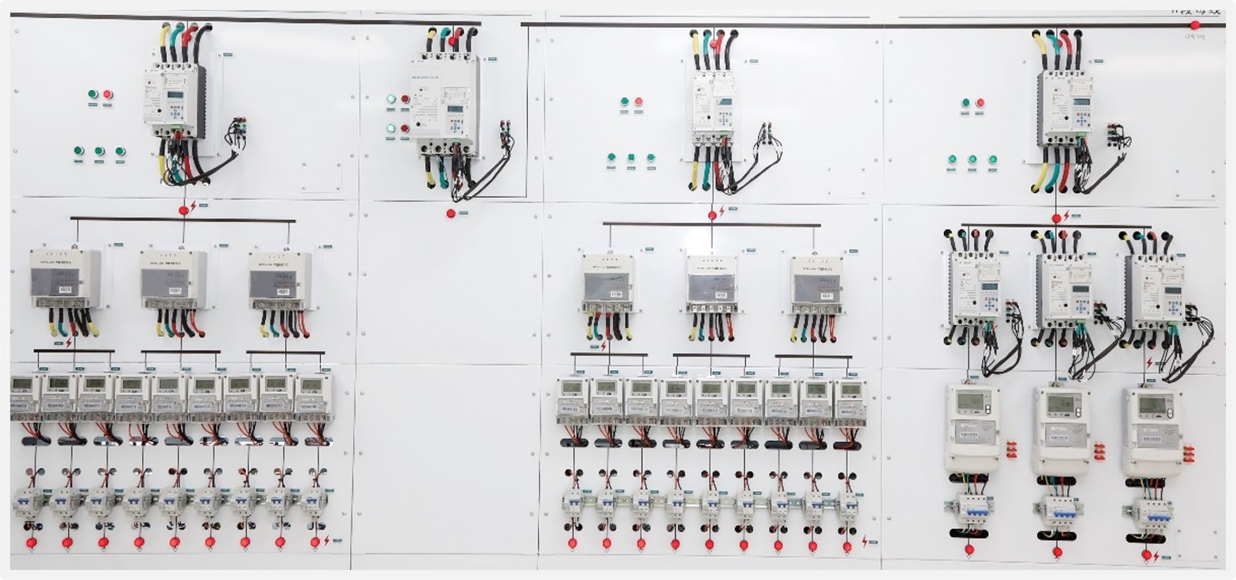
Physical frame of the urban intelligent distribution network testbed
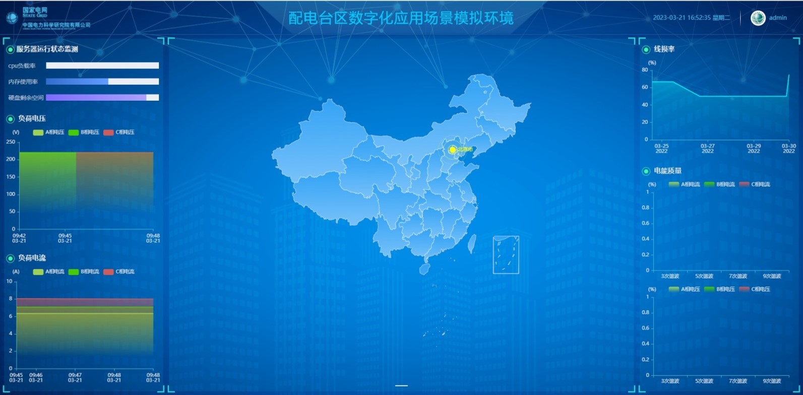
Cloud master station for monitoring, topology mapping, and remote maintenance

1. Hybrid Digital-Physical Platform with Plug-and-Play Topology Recognition

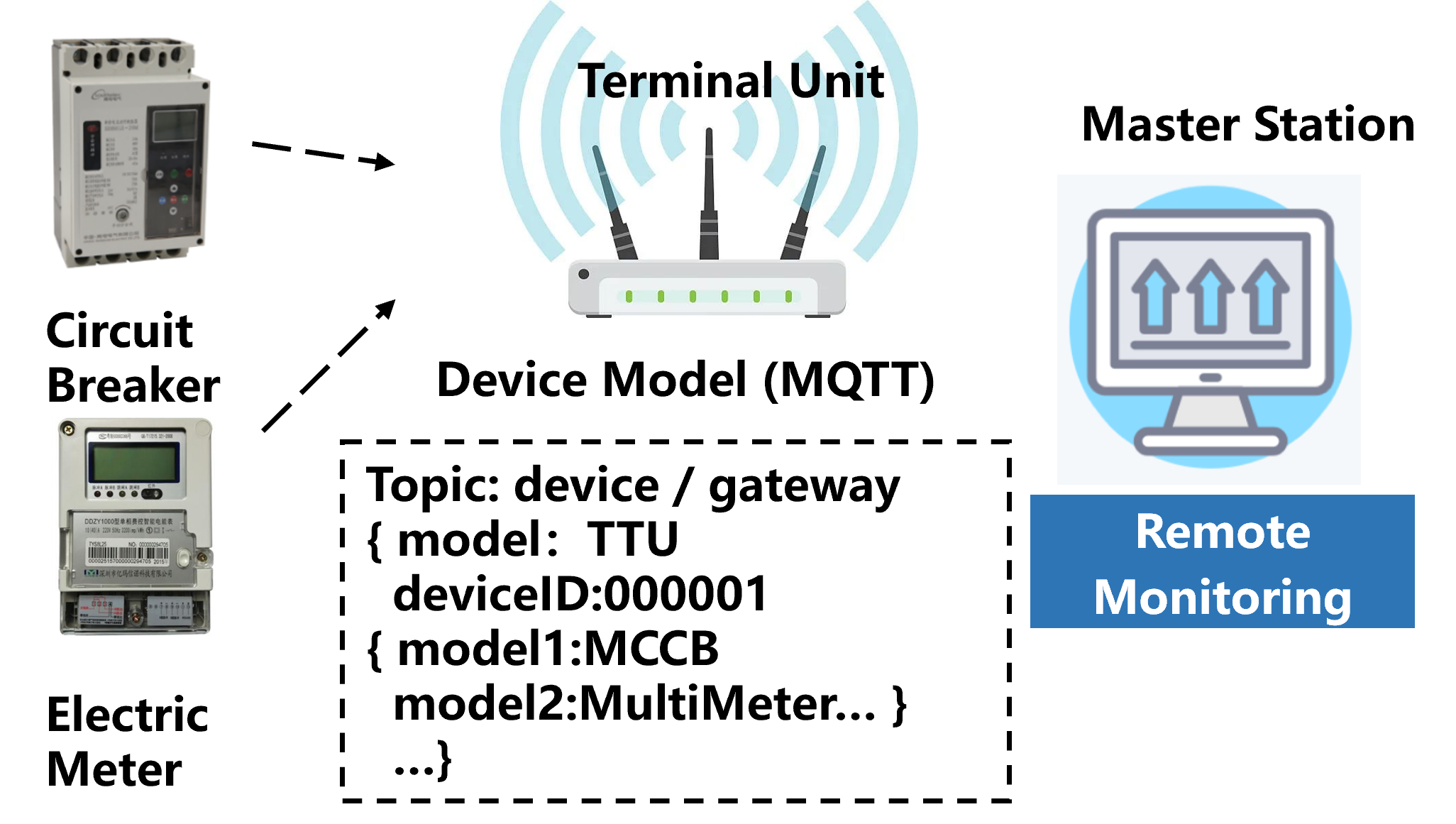
The testbed couples authentic physical equipment with a simulated digital network. Downstream devices are discovered through plug-and-play self-registration, and topology is reconstructed automatically so that the entire system can be monitored from a single cloud diagram.

Plug-and-play follows MQTT-based registration: (1) a newly installed device sends a modulation signal describing its identity to the terminal unit; (2) the terminal unit registers the device with the master station; (3) the device comes online on the cloud platform without manual configuration.

Plug-and-play scheme for smart distribution devices

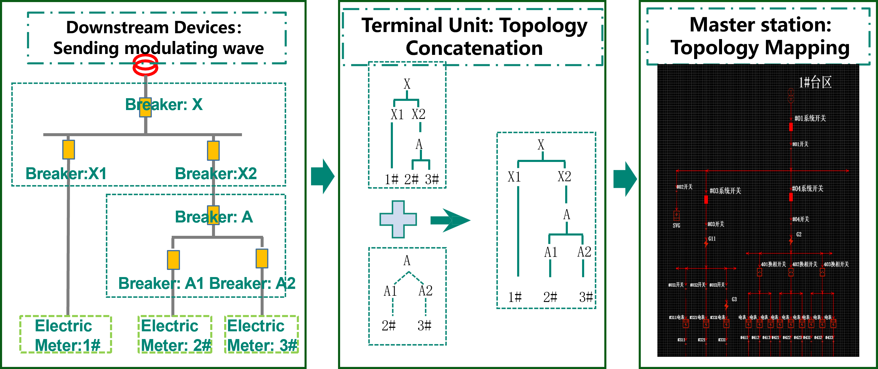
Topology recognition uses characteristic current signals emitted by downstream devices. The terminal unit identifies these signals and generates topology files; the master station maps the files to device records and draws the physical network on the cloud diagram.

Automatic topology recognition and cloud mapping

2. Automated Test Scenarios

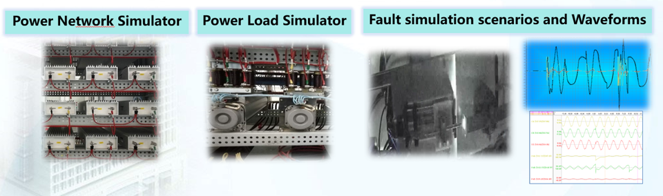
On this platform we built a full-scenario automatic testing environment with transient high-power sources and integrated RLC devices. The digital side reproduces the master station, feeders, loads, disturbances, and measuring devices; the physical side injects equivalent short-circuit and grounding faults. Terminal units under test are validated for data acquisition, device interaction, and remote control.

Simulation equipment for power sources, loads, and fault injection

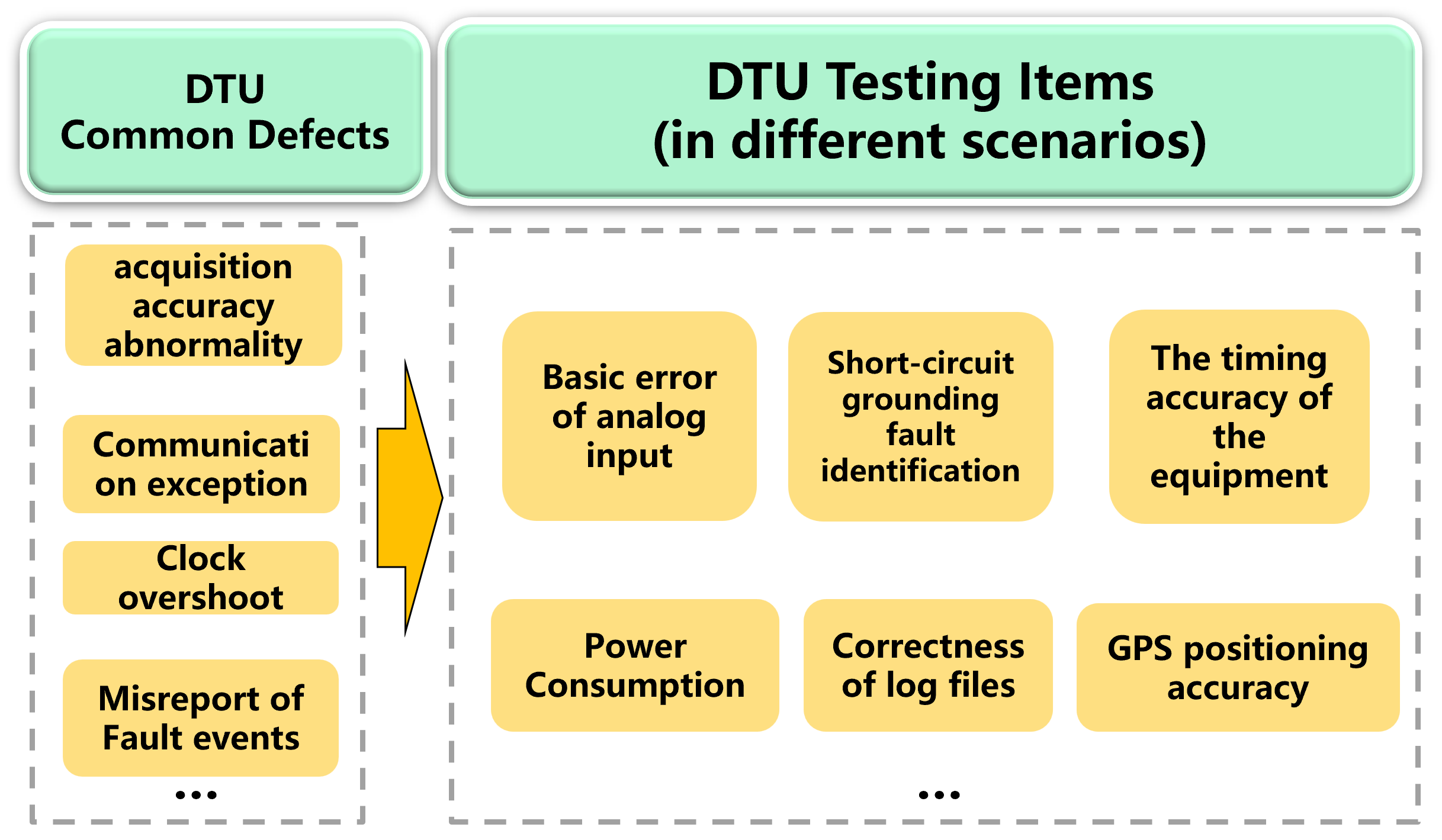
Test coverage is driven by typical terminal-unit defects: analog acquisition error, communication exceptions, clock drift, and false fault reports. Corresponding scenario families include analog-input accuracy, short-circuit and grounding fault identification, timing accuracy, power consumption, log-file correctness, and GPS positioning. In total, 96 standardized cases were compiled for system-level validation.
Common terminal-unit defects and corresponding test scenarios
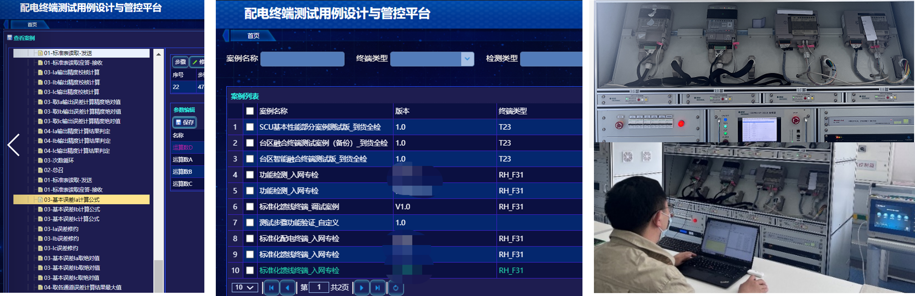
Test-case library and experiment on the standardized terminal-unit platform

3. Fault Identification Testing Example

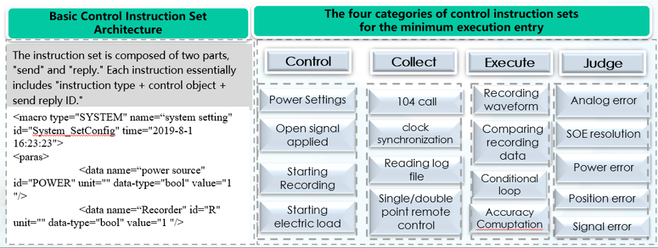
Test cases are generated by an in-house compilation system. Through an ask-reply interaction between the simulated master station and the hardware platform, we defined a standardized instruction set with four categories—control, collect, execute, and judge—at a visualized minimum execution scale. Users can compose and extend cases by combining these instructions.

Standardized compilation framework for automated test cases

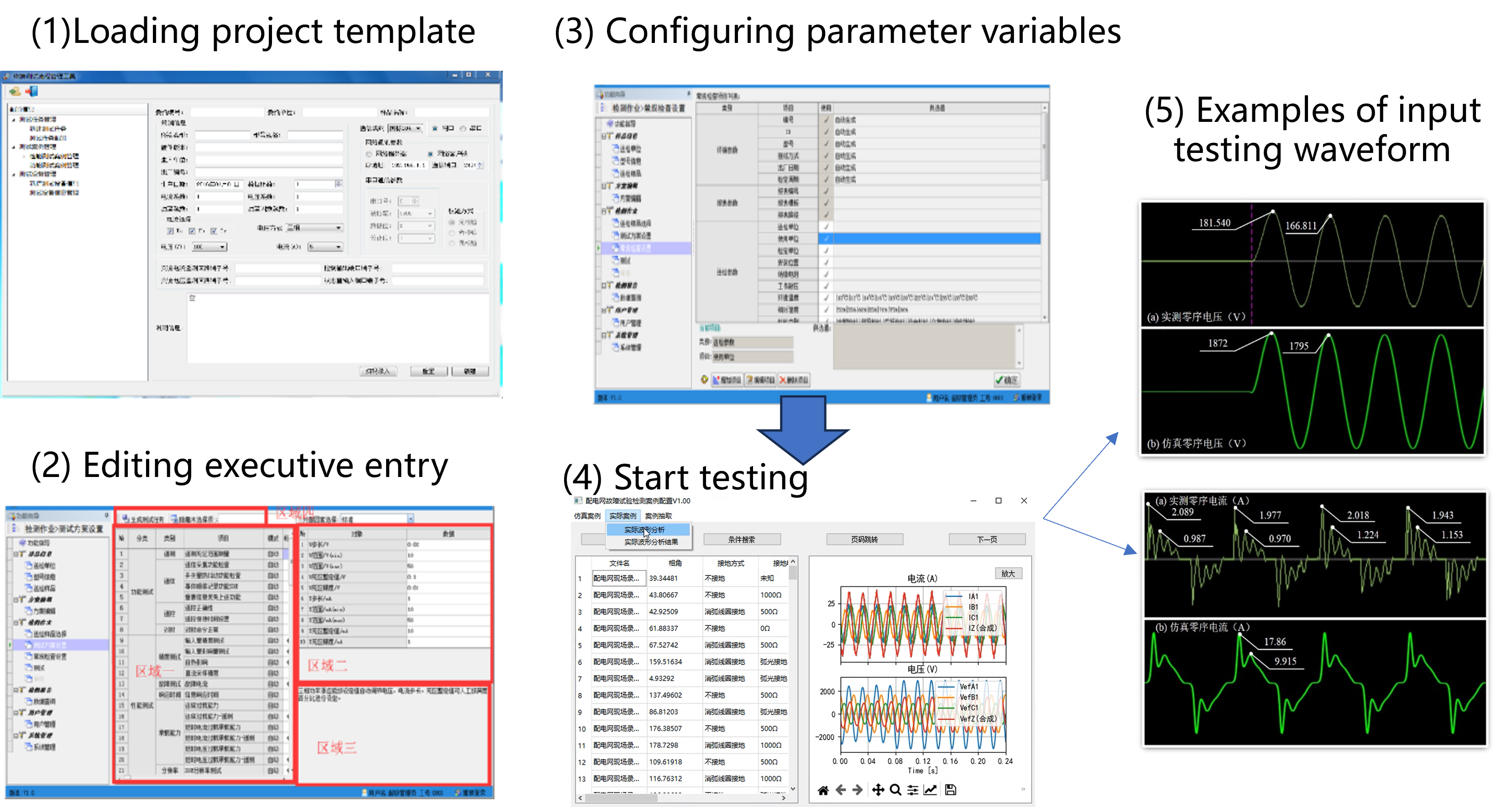
The figure below shows a fault-identification case for a terminal unit. The user selects a template from the compilation library, creates a fault-identification project, and configures variables. A typical sequence is: start-up, power-source start, terminal-unit reading, standard-meter reading, reading-error calculation, and alarm-status judgment.

Editing process of a terminal-unit fault-current identification case

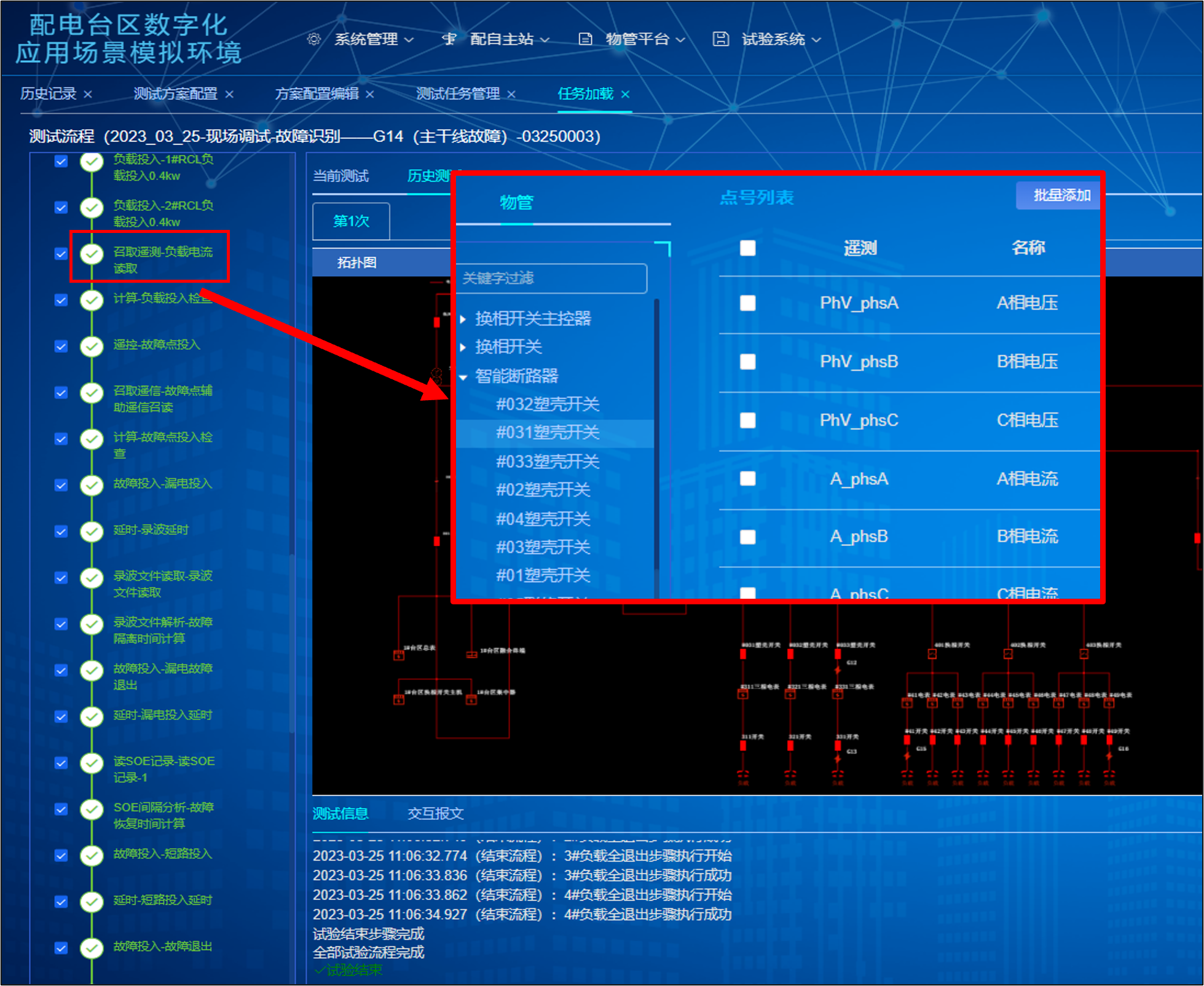
After compilation, the case is loaded onto the hybrid testbed. The example below is a main-line fault identification task: the platform injects the fault, the terminal unit reports telemetry, SOE, and recorded waveforms, and the master station automatically judges isolation and recovery against the expected sequence.

Automated execution of a main-line fault identification scenario