Feeder automation(FA), as a core component of the distribution automation system, plays a crucial role in quickly isolating faults and restoring power supply to non-faulty areas, thereby enhancing the reliability of power supply.
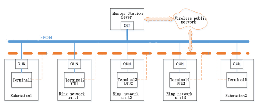
Distributed FA does not require decision-making by the master or substation. It primarily detects differences in characteristics such as short-circuit current on both sides of the faulted section and ground faults through the terminals themselves. Terminals establish a peer-to-peer communication network and assist each other in decision-making, ultimately automating fault location, isolation, and restoration of power supply in non-fault areas of the feeder. Additionally, it reports the processing procedure and results back to the distribution automation master station.
A complete fast-acting distributed FA action logic mainly includes seven key functional logics such as isolation, first-switch undervoltage protection, restoration, switch refusal judgment, malfunction protection, locking, and successful isolation judgment.
EXAMPLE:
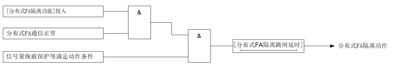
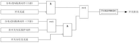
(1) The isolation function: The action logic in figure below, operates as follows: when the distributed FA isolation function is engaged and communication is normal, it acts after a delay once the conditions for action are met. This primarily involves two tripping actions: one upstream and one downstream of the fault point.
(2) The switch refusal judgment function: If a switch that needs to be opened exhibits a refusal to operate, action from its adjacent switches is required to expand the isolation range and achieve the excision of the faulted area. The functional logic, as shown in figure below.
Experiment of Main Line Failure:
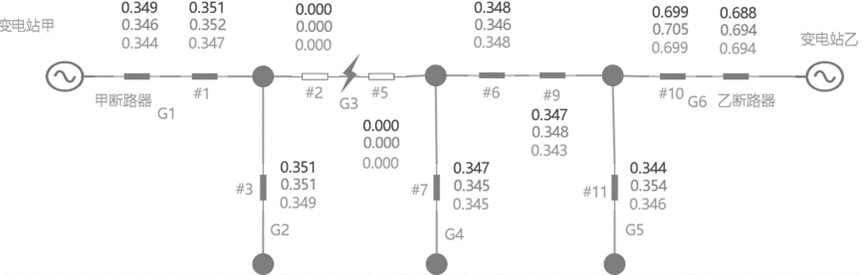
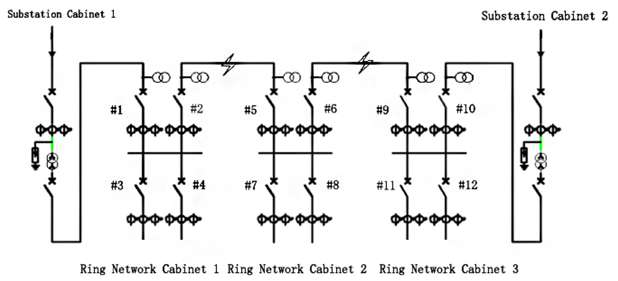
we use a 3 DTUs (each with 3 units) connected distributed FA dynamic mode testing system to introduce the testing process. The simplified primary feeder structure of the system is shown in Figure below. Each unit of DTU is connected to the circuit breaker 1-11,the circuit breaker 6 is opened to be used as a loop breaker. The peer to peer communication network has been established among the DTUs.
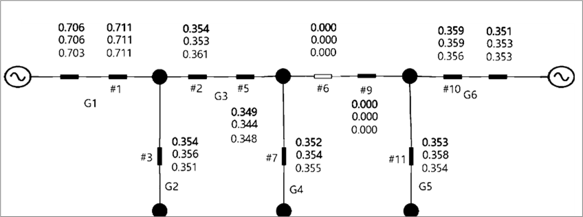
In order to simulate the short-circuit condition of main line, the system inputs the BC phase-to-phase short-circuit fault at G3 shown in Figure below. At this time, an overcurrent fault occurs downstream of the terminal (#2), #2 and #5 opens the connected breaker to isolate the fault section. The test master station receives the successful fault isolation remote signals sent by #2 and #5. After the fault is isolated, the loop breaker 6 is still open, and the non-faulty area downstream of #7 is powered off. When #6 detects the adjacent breaker isolation function is successfully performed, it will calculate the load of #7 to be transferred is 0.345A, which is less than the overload threshold 5A, and will closed breaker 6 to restore power to the downstream of #7. By observing the breakers action of 2, 5 and 6 and the remote signaling of the isolation and restoration of the distributed FA and the remote signaling of the breaker’s opening and closing position, it is judged that the distributed FA action of the terminal is successfully implemented.